Geoinput Node
The Geoinput node is a big part of what makes Nash so powerful, because it gives you access to a spatial toolset that can make your workflows more robust and useful.
Do you need to know if there are nearby work orders to a given record or address? Need to integrate your system with another custom spatially enabled application? Need to convert lat/long coordinates to another spatial projection? Want to find the nearest asset to the point where you’re standing?
If your answer is yes to any of these questions, then the Geoinput is your solution.

The Nash Geoinput node allows you to introduce geometry as inputs into your flow—inputs to be passed, modified, and selected. You add the Geoinput node to your flow, then select the type of geoinput from the list shown below that you want to employ:

Once you’ve configured your Geoinput, you’ll may use it in downstream nodes as a query parameter to return other features related to your geoinput selection, or you may pass the coordinates or data downstream for output. See more in the examples below.
Buffer
The Buffer geoinput allows you to use an input record from upstream to create a buffer around that record, a buffer to be used in a selection downstream. For example, if you have a fire hydrant record upstream in your flow data, you can create a 50 ft. buffer around that hydrant to be used downstream in the flow to select other features within the 50 ft. buffer. Here are a few tips to using the buffer:

Configuring the Buffer Option in the Geoinput node:
- After adding the Geoinput node to your flow, open the node editor.
- Choose “Buffer” from the Type dropdown menu.
- Choose a geometry server from the Connection (Geometry Server) dropdown. Make sure you have a connection defined at the Workspace level.
- In the Geometry field, you can either a) enter a specific set of coordinates (e.g. {x:-13049248, y:4016899.5, spatialReference:{wkid:102100}}) or b) enter in a value from an upstream node (e.g. ${I-1.GEOMETRY}). For this second option, make sure the upstream source node has its Geometry option checked, allowing the input geometry to be passed along downstream.
- In the Spatial Reference (WKID) field, enter the WKID of the source data. This is critical. If you don’t know the WKID of your data, go to the URL of your Esri map service to find it.
- In the Distance field, choose the size of the buffer you want to create.
- In the Units field, choose the measurement units of your buffer (Feet, Meters, Miles, Kilometers, or Yards).
Once you’ve finished defining the buffer, you need to use it as a spatial query in a downstream input. Here’s an example:
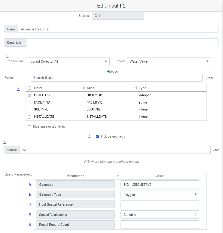
- Connection. After inserting a new input node, define the node’s connection to a data set with GIS coordinates.
- Fields. Choose the fields from the input you want to select.
- Include Geometry. Check the “Include Geometry” box to include the input record’s geometry in the results.
- Where. Define a where clause to filter the records selected (based on the input fields).Under the “Query Parameters” section, there are several options that allow you to use geometry as the where clause to filter the results set:
- Geometry: Here you can use the buffer polygon defined in G-1 (${G-1.GEOMETRY})
- Geometry Type: Here you match the type of geometry from the previous step — Polygon, in this case is that the buffer is.
- Input Spatial Reference: In this case, you leave this section blank, because it’s already been defined in the Geoinput node.
- Spatial Relationship: From the dropdown menu, choose “Contains” if you want to select new features that are contained wholly in the buffer polygon. For more information on the different spatial reference options, see https://developers.arcgis.com/documentation/mapping-apis-and-services/spatial-analysis/geometry-analysis/spatial-relationship/.
- Result Record Count: This field allows you to limit the result record count, which could be very large, depending on your buffer size. This option is useful when you’re testing your result sets.
That’s it. This configuration will return only the records that are contained in the buffer polygon defined in node G-1.
Distance
The Distance geoinput type allows you to find the distance between two geometries (typically two points) upstream in your flow. You add the spatial reference of your input geometry and the units you want your output to be.

Geocode
The Geocode geoinput returns the coordinates of an input containing a textural address (e.g. 123 E Main), like so:

GIS Extension
Allows you to use other GIS extensions not listed in the Geoinput options such as custom geoprocessing (gp) tools created for your organization or queries from a feature service. To use a GIS Extension geoinput with a gp tool, publish the service to either your organization’s Portal or ArcGIS Online account. To use the GIS Extension, you must navigate to your REST services and run the gp tool or the query that will be used. Once the gp tool or query is ran, the URL in the web browser navigation bar will have the parameters included. Copy the URL with the gp tool or query parameters included and paste them into the Record URL input box on the geoinput configuration. Click the get parameters button to the right of the Record URL input box and the parameters and fields will appear. Set the required parameters and select any needed fields.

Intersect
The Intersect geoinput returns the geometry (a point) where two input features intersect (can be used for points, lines and polygons).

Nearest Feature
The Nearest Feature option takes an input geometry (e.g. a point at which an inspection was performed) and returns the nearest GIS feature on a given layer (e.g. a transmission pole).

Figure 30: This example above finds the nearest GIS feature (a power pole in this case) to an input from Esri Quick Capture. The where clause is set to 1=1 to ensure we get all the possible records (poles) from the data source. The “Use geometry” check box is checked because we’re using the GIS geometry (the shape) from the TLAMP_Structures layer in GIS, rather than from separate X and Y coordinate fields. If we unchecked the box, the option for designating those fields would be visible.
Project
Project (as in Spatial Projection), allows you to convert a geometry to a new spatial reference, as shown below:

You need to add the JSON string, as shown above, noting the geometry type along with the geometry input itself. Then you provide the two spatial references (input and output).
Reverse Geocode
Reverse Geocode returns the nearest address of a set of coordinates. Choose a connection to a geocoding service and add the geometry value of the record you want to reverse geocode.
